ICP aka IEPE sensors are nice! Much easier to work with than the old stuff and still way better in performance than MEMS equivalents.
Beginning with those, I was frustrated with som ICP (Integrated CircuitPiezoelectric) vibration sensors not working.
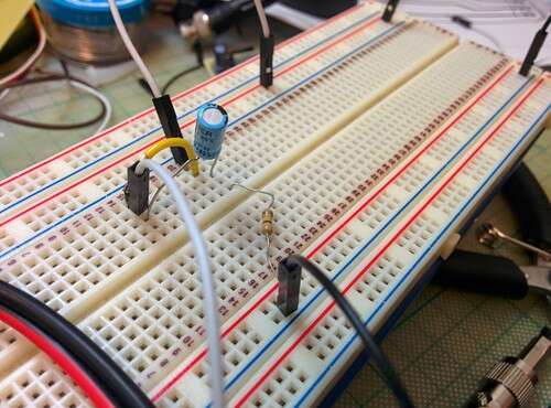
The sensor is driven by a dead simple circuit:
As you see:
A current limiting diode (surprisingly expensive)
A polarised capacitor (Tip: Use a tantalum capacitor for lower noise levels)
A 470K resistor
The circuit has worked before and even if it is difficult to mess, I checked more than 10 times the polarity and the continuity of the circuit.
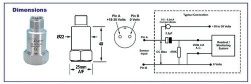
As you can see in the picture, there is one thing there called DC Bias. Just keep it on your mind.
Brief (fun?) theory
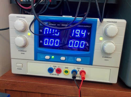
As I mentioned we are using an ICP sensor. These sensors are powered with a constant current DC source. The power supply is typically 18–30 Volts DC_current limited via a constant current diode between 0.5 and 8 mA (In my experience around 4mA is best). Typical battery operated supplies offer 2 mA of constant current to extend battery life while continuous monitoring systems offer more current in order to drive longer cables.
The signal output of an ICP sensor is a low impedance voltage signal proportional to the dynamic measurement such as force, pressure, or vibration. This voltage signal is carried on a DC bias voltage. The AC dynamic signal is superimposed on the DC bias voltage and is allowed to swing between the supply voltage and ground. Unlike an Operational Amplifier (Op Amp) that requires a plus and minus supply and allows the signal to “ride” on ground and “swing” between the plus and minus “rails,” the ICP sensor requires the output signal to be DC biased.
Let’s get troubleshooting!
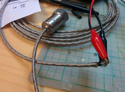
So, how do you check the sensor?
As you see I cannot break through it to see if I’ve fried it (these are pretty sturdy and frying them is harder than it sounds). I am also pretty sure that my circuit is good as it have worked perfectly before.
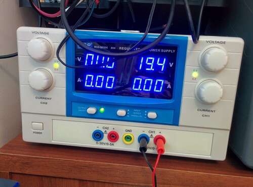
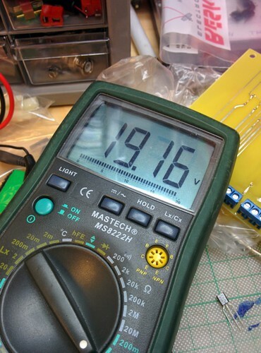
The DC Bias of the sensor can quickly and reliably show us if the sensor is working and if we have connected it correctly.
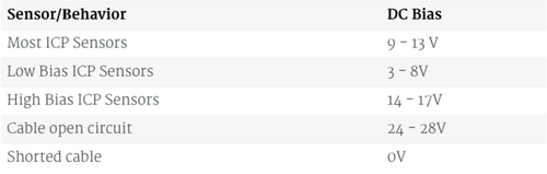
Below there is a table with common DC Bias voltages and their meaning:
Three scenarios are possible:
Generally, if you get around half your supply voltage you are good to go.
If you get 0 Volts you have probably shorten out something. Woops!
In my case, I got my supply voltage which means the connection to the sensor is faulty resulting to an open circuit. Check your cable!
Conclusions
As you see the DC Bias on these sensors is very useful for troubleshooting. So next time you bump on a wall like that you know what to do!
About Tasos Sangiotis
You can also find me on Twitter, on LinkedIn, and on Instagram. If you choose to wander this wasteland do so with caution. Consider this your final warning.